|
|
Base Unit Lift duct Thrust Duct Motor Mounts Front Cabin
Centre Cabin Air Duct Cover Skirt R/C Installation
R/C Installation
Radio equipment and batteries need to be positioned so that the model balances at the centre point. If running on water then a slightly rearward balance can be an advantage to help achieve the 'on hump' ride.
Speed controllers
The choice of speed controller should be given careful thought. Depending on the motors chosen, the current requirement will be in the tens of amps range. I originally used Electronize 15amp controllers but they tended to run very hot, even with extra heatsinks fitted. Eventually RCline RF10 units were used.
These have a 200amp continuous and 600amp peak specification and do not even get warm when operating in the model. The secret is the 600amp peak spec as when a motor is switched on and off to control it's speed the current peaks have been measured in excess of 200amps, only for a fraction of a second but the repetitive switching allows the heat dissipation to build up. These controllers have a separate sensor to check over temperature operation and shut down the controller until it cools down.
A lot of controllers on the market rely on the thermal shutdown of the FET which is too late in respect of the controllers operation.
Both controllers have a BEC but one is disabled to prevent receiver problems by removing the positive connection from the lead to the receiver.
The thrust controller has forward and reverse capability but the lift controller was reset to disable the reverse option.
Batteries
Several different batteries have been tried on the model, the first was a 12volt 4amp/hr lead acid. The model operated ok on land but would not achieve hump speed over water.
Next 10amp/hr ni cads were used at 4.8volts on the lift motor fitted with an 8 blade fan. This would lift the model as good as the previous set up and gave a half hour duration but again hump speed could not be achieved.
Finally the model now runs on 16 cells of 3000AH Ni MI's but only has a duration of 15 mins.
Through out these power experiments several props and fans have been used.
Receiver and servos
A Futaba Sky sport 6 on 40 MHz was used to control the model, only one servo being required for the rudders. The Frequency of 40Mhz is important as some might consider the model to come under model aircraft and use 35Mhz. Here in the UK a hovercraft is considered a 'land' vehicle and so joins model boats and cars in using the 27Mhz and 40Mhz radio bands. This is a legal requirement.
The receiver aerial is close wound on to a 4mm wooden dowel, the end is then extended and routes via a metal contact at deck level through the centre cabin to the scale aerial on it's roof. Before this was done the receiver picked up interference from the speed controllers and motors as it had to be routed round the model. I have extended aerials this way for many years without problems although the 'experts' will tell you it can't or shouldn't be done. On older receivers I used to fit a 10pf capacitor between the receiver aerial and it's extension.
Positioning of the equipment
|
|
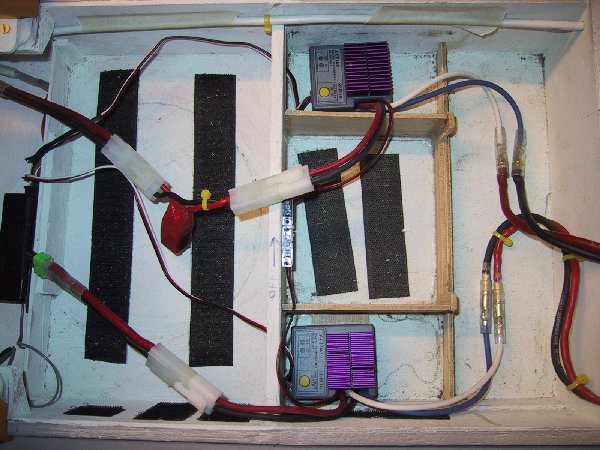
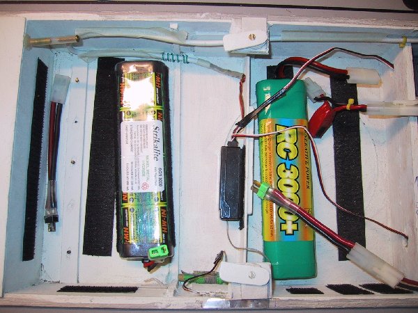
The receiver and one of the 8 cell battery packs are installed in the forward cabin. the second battery and the two speed controllers are mounted to the rear of the central cabin.
The rudder servo is mounted right at the rear on it's side to enable a direct link between the servo and the rudders.
Cabling between the batteries and respective controllers and between controllers and their motors is 60Amp silicone sleeved cable. This is to avoid too much voltage drop due to the length of the runs.